Operating Systems
IO Management
19 minute read
Notice a tyop typo? Please submit an issue or open a PR.
IO Management
I/O Devices
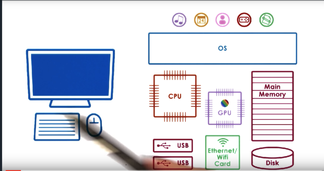
The execution of applications doesn't rely on only the CPU and memory, but other hardware components as well. Some of these components are specifically tied to receiving inputs or directing outputs, and these are referred to as I/O devices.
Examples of I/O devices include
- keyboards
- microphones
- displays
- speakers
- mice
- network interface cards
I/O Device Features
The device space is extremely diverse.
Devices come in all shapes and sizes with a lot of variability in their hardware architecture, functionality, and interfaces. Our discussion will focus on the key features of a device that enable its integration into a system.
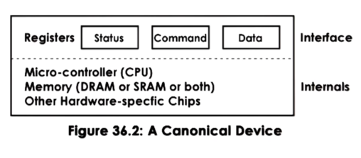
In general, a device will have a set of control registers which can be accessed by the CPU and permit CPU/device interactions. These registers are typically divided into: command registers, that the CPU uses to control the device; data registers, that are used by the CPU to transfer data in and out of the device; status registers that are used by the CPU to understand what is happening on the device.
Internally, the device will incorporate all other device-specific logic. This will include the microcontroller - which is basically the device's CPU - on device memory, as well as any other logic needed by the device. For example, some devices may need chips for converting analog to digital signals. As another example, network devices may need chips to interact with the physical network medium, be it optics or copper wire.
CPU Device Interconnect
Devices interface with the rest of the system via a controller that is typically integrated as part of the device packaging that is used to connect the device with the rest of the CPU complex via some CPU/device interconnect.
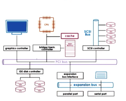
In this figure, all of the the controllers are connected to the rest of the system via a Peripheral Component Interconnect (PCI) bus.
Modern platforms typically support PCI Express, which is more technologically advanced than PCI-X and PCI. PCI Express has more bandwidth, is faster, has lower latency, and supports more devices than PCI-X. For compatibility reasons, though, most platforms will include PCI-X which follows the original PCI standard.
The PCI bus is not the only possible interconnect that can be present in a system. In this example, we see a SCSI bus that connects SCSI disks and an expansion (peripheral) bus that connects things like keyboards.
The device controllers determine what type of interconnect a device can attach to. Bridging controllers can handle any difference between different types of interconnects.
Device Drivers
Operating systems support devices via device drivers.
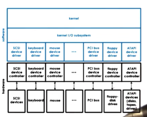
Device drivers are device-specific software components. The operating systems needs to include a device driver for every type of device that is included in the system.
Device drivers are responsible for all aspects of device access, management and control. This includes logic that determines how requests are passed from higher level components to the device and how those components respond to errors or notifications from the device. Generally, device drivers govern any device-specific configuration/operation details.
The manufacturer of a device is responsible for making drivers available for all the operating systems where their device will be used. For example, you may often have to download printer drivers from HP when you buy a new HP printer.
Operating systems standardize their interfaces to device drivers. Typically this is done by providing some device driver framework, so that device manufacturers can develop their drivers within that framework. This helps to decouple the operating system from a fixed set of specific devices, which makes the operating system independent of the devices it supports while also allowing it to support many different devices.
Types of Devices
Devices can be roughly grouped into categories.
Block devices - like disks - operate at the granularity of blocks of data that are delivered to and from the device via the CPU interconnect. A key property of block devices is that individual blocks can be accessed. If you have ten blocks of data on a disk, you can directly request the ninth one.
Character devices - like keyboards - work with a serial sequence of characters and support a get/put character interface.
Network devices are somewhere in between. They deliver more than a character at a time, but their granularity is not a fixed block size. They are more like a stream of data chunks of potentially different sizes.
The interface a devices exposes to the operating system is standardized based on the type of device. All block devices should support operations for reading and writing a block of data. All character devices should support operations to get and put a character.
Internally, the operating system maintains some representation for each of the devices available on the platform. This is typically done using a file abstraction where each file represents a device. This allows the operating system to interact with devices via the same interface is already maintains for interacting with files. That being said, these operations will be handled in some device specific manner.
On UNIX-like systems, all devices appear as files under the /dev directory. They are treated by the filesystems tmpfs and devfs.
CPU/Device Interactions
The device registers appear to the CPU as memory locations at a specific physical address. When the CPU writes to these locations, the integrated PCI controller realizes that these accesses should be routed to the appropriate device.
This means that a portion of the physical memory on the system is dedicated for device interactions. We call this memory-mapped I/O. The portion of the memory that is reserved for these interactions is controlled by the Base Address Registers (BAR). These registers get configured during the boot process in accordance to the PCI protocol.
In addition, the CPU can access devices via special instructions. x86 platforms specify certain in/out instructions that are used for accessing devices. Each instruction needs to specify the target device - the I/O port - as well as some value that will be passed to the device. This model is called the I/O Port Model.
The path from the device to the CPU complex can take two routes. Devices can generate interrupts to the CPU. CPUs can poll devices by reading their status registers to determine if they have some response/data for the CPU.
With interrupts, the downside is the interrupt handlers. There are the actual steps involved in the interrupt handler that cost CPU cycles. There may be setting/resetting of interrupt masks as well as more indirect effects due to cache pollution.
That being said, interrupts can be triggered by the device as soon as the device has information for the CPU.
For polling, the OS has the opportunity to choose when it will poll. The OS can choose to poll at times when cache pollution will be at its lowest. However, this strategy can introduce delay in how the event is observed or handled, since the handling happens at some point after the event has been generated by device. In addition, too much polling may introduce CPU overhead that may not be affordable.
Device Access PIO
With just basic support from an interconnect like PCI, a CPU can request an operation from an I/O device using programmed I/O (PIO). This method requires no extra hardware support.
The CPU issues instructions by writing into the command registers of the device. The CPU controls data movement to/from the device by reading/writing into the data registers for the device.
Let's consider how a process running on the CPU transmits a network packet via a network interface card (NIC) device.
First, the CPU needs to write to a command register on the device. This command needs to instruct the device that it needs to perform a transmission of the data that the CPU will provide. The CPU then needs to copy the packet into the data registers, and will repeat as many times as necessary until the entire packet is sent.
For example, we may have a 1500B packet that we wish to transmit using 8 byte data registers. The whole operation will take 1 CPU access to the command register and then 188 - 1500 / 8 rounded up - accesses to the data register. In total, 189 CPU accesses are needed to transmit the packet.
Device Access DMA
An alternative to using PIO is to use Direct Memory Access (DMA) supported devices. This method requires additional hard support in the form of a DMA controller.
For devices that have DMA support, the CPU still writes commands directly to the command registers on the device. However, the data movement is controlled by configuring the DMA controller to know which data needs to be moved from memory to the device, and vice versa.
Let's consider how a process running on the CPU transmits a network packet via a network interface card (NIC) device.
First, the CPU needs to write to a command register on the device. This command needs to instruct the device that it needs to perform a transmission of the data that the CPU will provide.
This command needs to be accompanied with an operation that configures the DMA controller with the information about the memory address and size of the buffer that is holding the network packet.
If we have a 1500B packet that we wish to transmit using 8 byte data registers, the whole operation will take 1 CPU access to the command register and then 1 DMA configuration operation.
DMA configuration is not a trivial operation! It takes many more cycles than a memory access. For smaller transfers, PIO will still be more efficient.
In order for DMA to work, the data buffer must be in physical memory until the transfer completes. It cannot be swapped out to disk, since the DMA controller only has access to physical memory. This means that the memory regions involved in DMA are pinned. They are non-swappable.
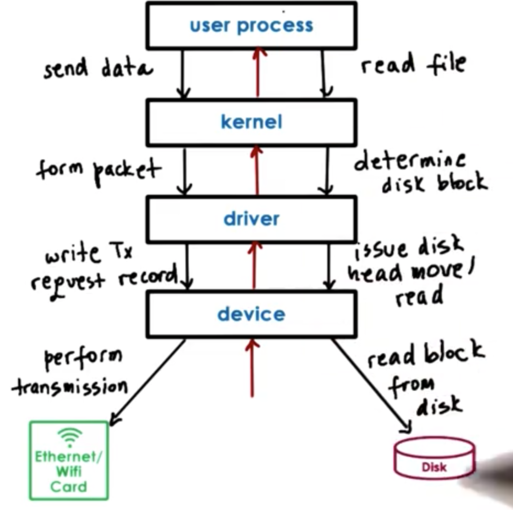
Typical Device Access
When a user process needs to perform an operation that requires a device, the process will make a system call specifying the appropriate operation.
The operating system will then run the in-kernel stack associated with the specific device, and may perform some preprocessing to prepare the data received by the user process for the device. For example, the kernel may form a TCP/IP packet from an unformatted buffer.
Then the operating system will invoke the appropriate device driver for the device. The device driver will then perform the configuration of the request to the device. For example, a device driver to a network interface card will write a record that configures the device to perform a transmission of the packet sent from the operating system.
The device drivers issue commands and send data using the appropriate PIO or DMA operations. The drivers are responsible for ensuring that any commands and data needed by the device are not overwritten or undelivered.
Finally, once the device is configured, the device will perform the actual request. For example, a NIC will actually transmit the packet onto the network.
Any results/events originating on the device will traverse this chain in reverse: from the device to the driver to the kernel and finally into the user process.
OS Bypass
It is not necessary to go through the kernel to get to a device. It is possible to configure some devices to be accessible directly from user level. This is called operating system bypass. In OS bypass, any memory/registers assigned for use by the device is directly available to a user process.
The OS is involved in making the device registers available to the user process on create, but then is out of the way.
Since we don't want to interact with the kernel in order to control the device, we need a user-level driver - basically a library - that the user process links in order to interact with the device. These libraries, like the kernel-level drivers, will usually be provided by the device manufacturers.
The OS has to retain some coarse-grain control. For example, the OS can still enable/disable a device or add permissions to add more processes to use the device. The device must have enough registers so that the OS can map some of them into one or more user processes while still retaining access to a few registers itself so it can interact with the device at a high-level.
When the device needs to pass some data to one of the processes interacting with it, the device must figure out which process the data belongs to. The device must perform some protocol functionality in order to demultiplex different chunks of data that belong to different processes. Normally, the kernel performs the demultiplexing, but in OS bypass that responsibility is left to the device itself.
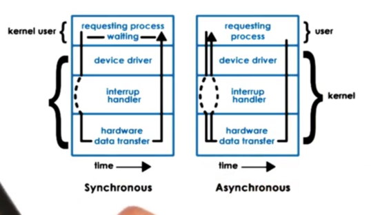
Sync vs. Async Access
When an I/O request is made, the user process typically requires some type of response from the device, even if it just an acknowledgement.
What happens to a user thread once an I/O request is made depends on whether the request was synchronous or asynchronous.
For synchronous operations, the calling thread will block. The OS kernel will place the thread on the corresponding wait queue associated with the device, and thread will eventually become runnable again when the response to its request becomes available.
With asynchronous operations, the thread is allowed to continue as soon as it issues the request. At some later time, the user process can be allowed to check if the response is available. Alternatively, the kernel can notify the process that the operation is complete and that the results are available.
Remember when we talked about Flash, we discussed that the implementation mimicked asynchronous I/O by delegating all I/O calls to special helper threads. Here we are talking about true, OS-supported asynchronous I/O.
Block Device Stack
Block devices, like disks, are typically used for storage, and the typical storage-related abstraction used by applications is the file. A file is a logical storage unit which maps to some underlying physical storage location. At the level of the user process we don't think about interacting with blocks of storage. We think about interacting with files.
Below the file-based interface used by applications is the file system. The file system will receive read/write operations from a user process for a given file, and will have the information to find the file, determine if the user process can access it and which portion to access. The operating system can then actually perform the access.
Operating systems allow for a filesystem to be modified or completely replaced with a different filesystem. To make this easy, operating systems standardize the filesystem interface that is exposed to a user process. The standardized API is the POSIX API, which includes the system calls for read and write. The result is that filesystems can be swapped out without breaking user applications/
If the files are stored on block devices, the filesystem will need to interact with these devices via their device drivers. Different types of block devices can be used for the physical storage and the actual interaction with them will require certain protocol-specific APIs. Even though the devices may all be block devices, there can and often will be differences among their APIs.
In order to mask these device-specific differences, the block device stack introduces another layer: the generic block layer. The intent of this layer is to provide a standard for a particular operating system to all types of block devices. The full device features are still available and accessible through the device driver, but are abstracted away from the filesystem itself.
Thus, in the same way that the filesystem provides a consistent file API to user processes, the operating system provides a consistent block API to the filesystem.
Virtual File System
What if we want to make sure that a user application can seamlessly see files across multiple devices as a single, coherent filesystem?
What if different types of devices work better with different filesystem implementations?
What if files are not even local to a machine, and are accessed over the network?
To solve the underlying problems that these questions pose, operating systems like Linux include a virtual filesystem (VFS) layer. This layer hides all details regarding the underlying filesystem(s) from the higher level consumers.
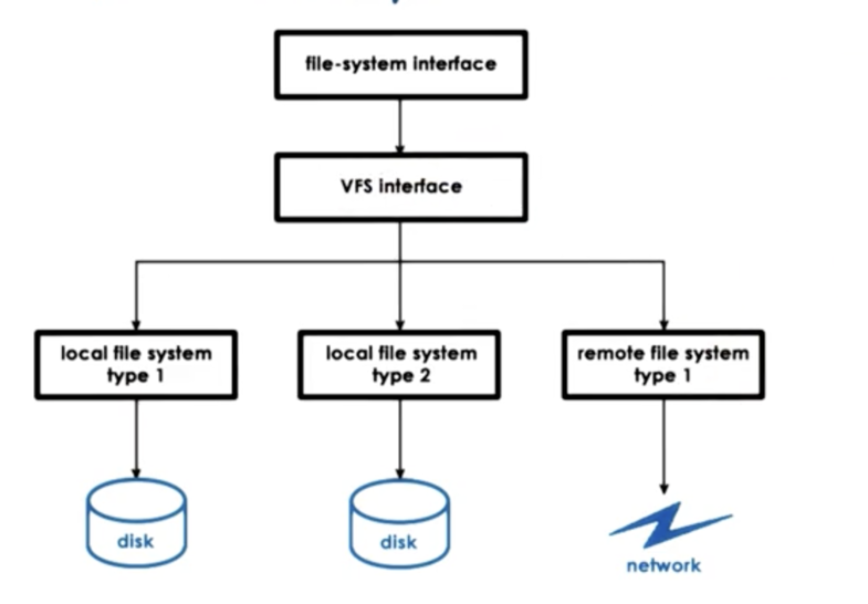
Applications continue to interact with the VFS using the same POSIX API as before, and the VFS specifies a more detailed set of filesystem-related abstractions that every single underlying filesystem must implement.
Virtual File system Abstractions
The file abstraction represent the elements on which the VFS operates.
The OS abstracts files via file descriptors. A file descriptor is an integer that is created when a file is first opened. There are many operations that can be supported on files using a file descriptor, such as read, write and close.
For each file the VFS maintains a persistent data structure called an inode. The inode maintains a list of all of data blocks corresponding to the file. In this way, the inode is the "index node" for a file. The inode also contains other information for that file, like permissions associated with the file, the size of the file, and other metadata. Inodes are important because file do not need to be stored contiguously on disk. Blocks for a file may exist all over the storage media, making it important to maintain this index.
To help with certain operations on directories, Linux maintains a data structure called a dentry (directory entry). Each dentry object corresponds to a single path component that is being traversed as we are trying to reach a particular file. For instance, if we are trying to access a file in /users/ada, the filesystem will create a dentry for every path component - for / , /users and /users/ada.
This is useful because when we need to find another file in /users/ada, we don't need to go through the entire path and re-read the files that correspond to all of the directories in order to get to the /users/ada directory. The filesystem will maintain a dentry cache containing all of the directories that we have previously visited. Note that dentry objects live only in memory; they are not persisted.
Finally, the superblock abstraction provides information about how a particular filesystem is laid out on some storage device. The data structure maintains a map that the filesystem uses so it can figure out how it has organized the persistent data elements like inodes and the data blocks that belong to different files.
Each file system maintains some additional metadata in the superblock. Different file systems store different metadata.
VFS on Disk
The virtual file system data structures are software entities. They are created and maintained by the operating system file system component.
Other than the dentries, the remaining components of the filesystem will correspond to blocks that are present on disk. The files are written to disk as blocks. The inodes - which track all of the blocks that correspond to a file - are persisted as well in a block.
To make sense of all of this - that is, to understand which blocks hold data, which blocks hold inodes and which blocks are free - the superblock maintains an overall map of all of the disks on a particular device. This map is used both for allocation and lookup.
ext2: Second Extended Filesystem
The ext2 filesystem was the default filesystem in Linux until it was replaced by ext3 and ext4 more recently.
A disk partition that is used as a ext2 Linux filesystem looks as follows.
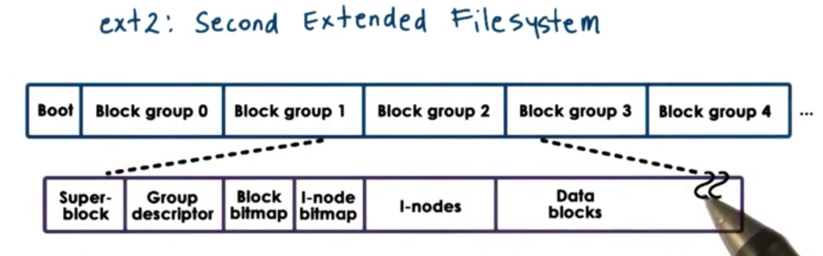
The first block is not used by Linux and is often used to boot the system.
The rest of the partition is divided into block groups. The size of these block groups have no correlation to the physics of the actual disk these group abstract.
Each block group contains several blocks.
The first block is the super block, which contains information about the overall block group:
- number of inodes
- number of disk blocks
- start of free blocks
The overall state of the block group is further described by the group descriptor, which contains information about:
- bitmaps
- number of free nodes
- number of directories
Bitmaps are used to quickly find free blocks and inodes. Higher level allocators can read the bitmaps to easily determine which blocks and inodes are free and which are in use.
The inodes are numbered from 1 to some maximum value. Every inode in ext2 is a 128B data structure that describes exactly one file. The inode will contain information about file ownership as well as pointers to the actual data blocks that hold the data.
Finally, the block group contains the actual data blocks themselves that hold the data.
inodes
Inodes play a key role in organizing how files are stored on disk because they essentially integrate an index of all of the disk blocks that correspond to a particular file.
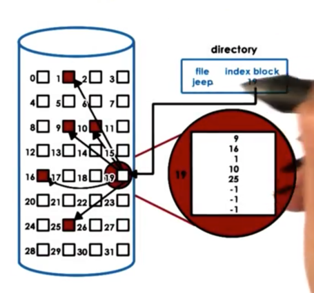
A file is uniquely identified by its inode. The inode contains a list of all of the blocks that correspond to the actual file. In addition to the list of blocks, an inode also contains additional metadata information.
The file shown above has 5 blocks allocated to it. If we need more storage for the file, the filesystem can allocate a free block, and simply update the inode to contain a sixth entry, pointing to the newly allocated block.
The benefit of this approach is that it is easy to perform both sequential and random accesses to the file.
The downside of this approach is that there is a limit on the file size for files that can be indexed using this data structure. For example, if we have a 128B inode containing 4B block pointers, we can only address 32 blocks. If each block can store 1Kb of information, our file size limit is 32Kb, which is too restrictive.
inodes with Indirect Pointers
One way to solve the issue of file size limits is to use indirect pointers.
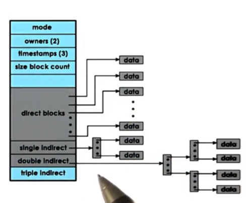
The first section of blocks contain blocks that point directly to data. The direct pointers will point to 1kb per entry.
To extend the number a disk blocks that can be addressed via a single inode element, while also keeping the size of the inode small, we can use indirect pointers.
An indirect pointer will point to a block of pointers, where each pointer points to data. Given that a block contains 1kB of space, and a pointer is 4B large, a single indirect pointer can point to 256KB of file content.
A double indirect pointer will point to a block of single indirect pointers, while will point to pointers to data. This means that a single double indirect pointer can point to 2562561KB = 64MB of file content.
The benefits of indirect pointers is that it allows us to use relatively small inodes while being able to address larger and large files.
The downside of indirect pointers is that file access is slowed down. Without any indirect pointers, we have at most two disk accesses to get a block of content: one access for the inode, one access for the block. With double indirect pointers, we double the number of accesses we need to make: inode + block + two pointers.
Disk Access Optimizations
Filesystems use several techniques to try to minimize the accesses to disk and to improve the file access overheads.
For example, filesystems rely on buffer caches in main memory to reduce the number of disk accesses. Content will be written to and read from these caches, and periodically will be flushed to disk. File systems support this operation via the fsync system call.
Another component that helps reduce the file access overhead is I/O scheduling. A main goal of I/O scheduling is to reduce the disk head movement, which is a slow operation. I/O schedulers can achieve this by maximizing sequential accesses over random accesses.
For example, if a disk head is at block 7, and a request to write at block 25 comes in, followed by a request to write at block 17, the I/O scheduler may re-order the requests so it can write to block 17 on its way to block 25 instead of having to backtrack.
Another useful technique is prefetching. Since there is often a lot of locality in how a file is accessed, cache hits can be increased by fetching nearby blocks during a request.
For example, if a read request comes in for block 17, the filesystem may also read block 18 and 19 into its cache. It prefetches these blocks because it is likely that they will also be read.
This does use more disk bandwidth to move more data from disk into main memory, but it can significantly reduce the access latency by increasing the cache hit rate.
A final useful technique is journaling. I/O scheduling reduces random access, but it still keeps the data in memory. Blocks 17 and 25 are still in memory waiting for the I/O scheduler to interleave them in the right way. That means that if the system crashes these data blocks will be lost.
As opposed to writing out the data in the proper disk location, which would require a lot of random disk access, in journaling we write updates to a log. The log will contain some description of the write that needs to take place, such as the block, the offset, and the content to be written. The writes described in the log are periodically applied to proper disk locations.
OMSCS Notes is made with in NYC by Matt Schlenker.
Copyright © 2019-2023. All rights reserved.
privacy policy