Robotics Ai Techniques
Kinematic Bicycle Model: 101
11 minute read
Notice a tyop typo? Please submit an issue or open a PR.
Kinematic Bicycle Model: 101
Topics
This lecture introduces a kinematic motion model known as the bicycle model. After we learn the basics of the model, we will examine the types of problems it can help us solve, and we will step through one such problem to solidify our grasp of the material. Along the way, we will derive all the necessary formulas.
Representation
We typically represent our robots as cars; however, we won't derive the kinematic formulas for a four-wheeled vehicle in this lecture. Instead, we use the bicycle model, which models a two-wheeled vehicle. This model approximates the four-wheeled model while also making the calculations easier.
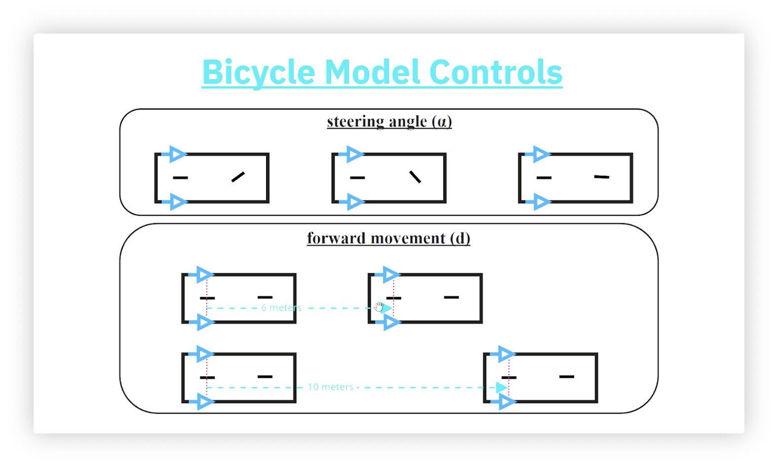
Controls
The bicycle model has two controls. The steering angle, , is the angle that the front wheel makes with the orientation of the vehicle. is positive if the wheel is turned to the left, negative if the wheel is turned to the right, and zero if the wheel is straight. The forward movement, , is the difference between the position of the rear axle before and after movement. Unlike the front axle, the rear axle remains parallel to the orientation of the robot and does not swivel.
Robot Pose
The robot pose consists of three properties:
- , the x-coordinate of the robot's position
- , the y-coordinate of the robot's position
- , the robot's orientation (measured from the x-axis)
In the following picture, robots A and C have the same orientation, as do robots B and E, while robots D and E have the same position. None of the robots have the same pose.
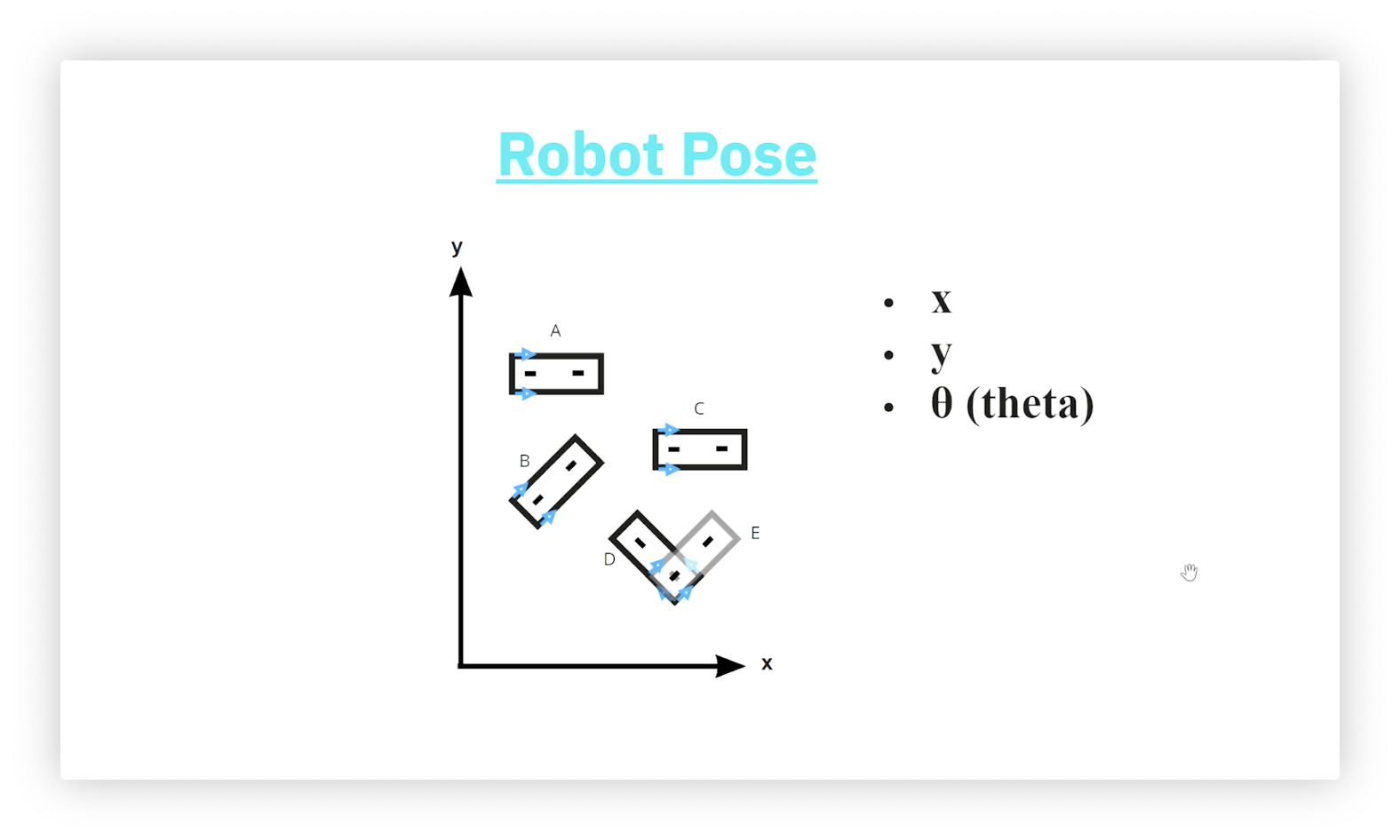
Confused as to why robots D and E have the same position? D and E are moving away from each other horizontally, so the image above shows their back axles overlapping, not the front axle of D overlapping the back axle of E. Remember that the arrows indicate the direction of motion.
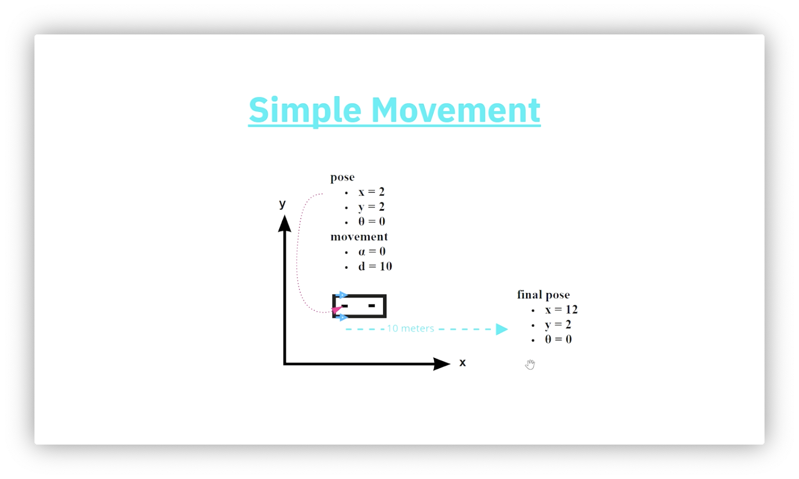
Simple Movement - Horizontal
We can choose to engage only one of the controls when using the bicycle model. Let's apply a forward movement. The diagram below shows a robot whose current pose is . After applying a forward movement of ten, what is the robot's pose? Since the robot's current orientation is parallel to the x-axis, the forward movement only affects the horizontal component of the pose. We add ten to that component for a final pose of .
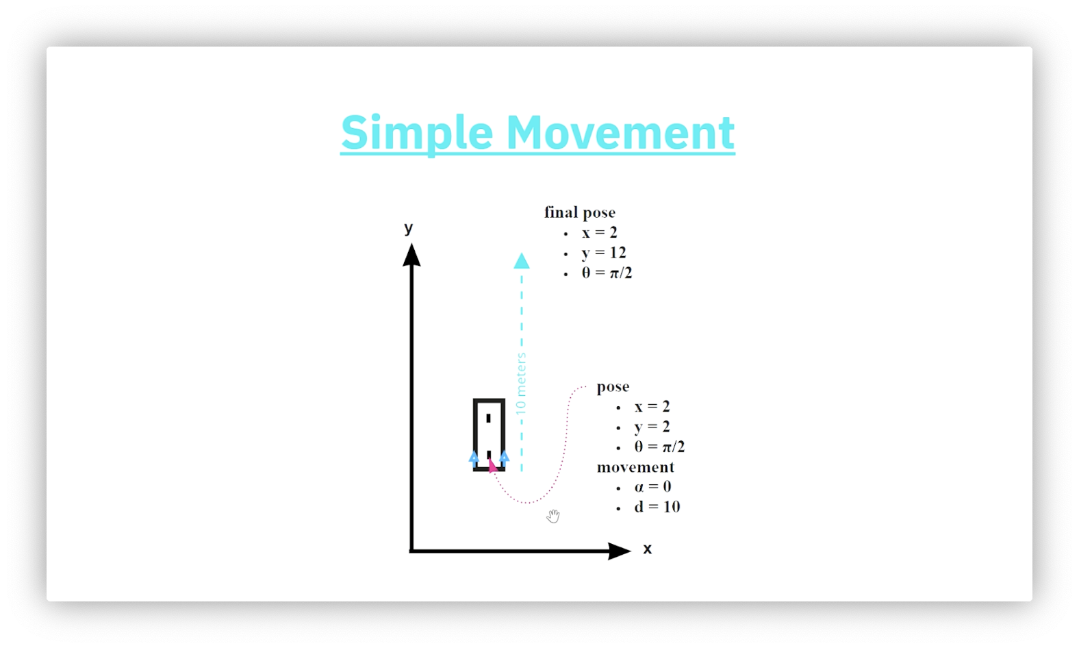
Simple Movement - Vertical
The diagram below shows a robot whose current pose is . After applying a forward movement of ten, what is the robot's pose? Since the robot's current orientation is parallel to the y-axis, the forward movement only affects the vertical component of the pose. We add ten to that component for a final pose of .
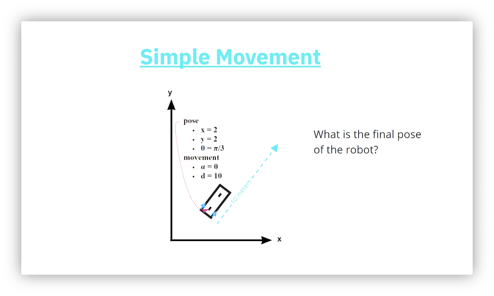
Quiz: Simple Movement - Diagonal
When the robot is not parallel to either axis, we need trigonometry to determine the result of applying the forward movement. Given a robot with an initial pose of , what is the robot's pose after applying a forward motion of ten?
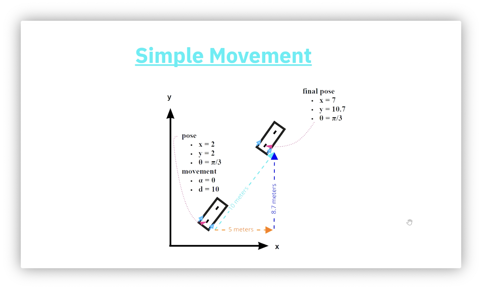
Quiz Solution: Simple Movement - Diagonal
The horizontal component of the forward movement, , is the product of and the cosine of ; that is: . Similarly, the vertical component of is times the sine of : . Adding the deltas to their corresponding components of the original pose gives us the final pose: .
Quiz: Distinct Tracks A
Imagine that our robot's wheels emit ink as they roll across a surface during a movement. If the robot has a zero steering angle, would we expect to see one or two lines of ink (tracks) after a movement? Assume we are using a two-wheeled bicycle, not a four-wheeled car.
Quiz Solution: Distinct Tracks A
We expect to see a single track after the movement.
Quiz: Track Shape
Now let's engage both controls in the model. If the robot uses a positive steering angle and travels forward, what shape will the track it leaves behind generate?
- A heart
- A triangle
- A circle
- An oval
Quiz Solution: Track Shape
The track left behind by a robot with a constant, non-zero steering angle and enough forward movement forms a circle.
Quiz: Distinct Tracks B
If we engage in this compound movement involving both the steering angle and the forward motion, would we expect to see a single track or two tracks after the movement?
Quiz Solution: Distinct Tracks B
In this case, the movement will produce two distinct circular tracks with the same center. The rear axle always creates the track with the smaller radius, and it is this track we concern ourselves with for this lesson.
Problem to Solve
Here is the general problem we can solve using the bicycle model: given a starting robot pose and a set of controls - some forward motion and some constant, fixed steering angle - what is the resulting pose after applying these controls?
Solution Steps
We solve the general problem described above in four steps.
- Determine the radius of the circle.
- Calculate the center of the circle using the radius and robot orientation. This point serves as our reference point.
- Determine the turning angle around the circle using the distance traveled.
- Determine the offset using the original orientation and the turning angle.
What is "the circle"? Remember, robot movement that combines forward motion with a nonzero steering angle produces circular motion, just as pedaling a bicycle with the handlebars turned causes you to ride in circles.
Quiz: Circle Center
What happens to the center of the circle as the steering angle increases?
- It moves closer to the robot
- It moves further from the robot
- It stays in the same place
- None of the above
Quiz Solution: Circle Center
As we increase the steering angle, the center of the circle moves closer to the robot.
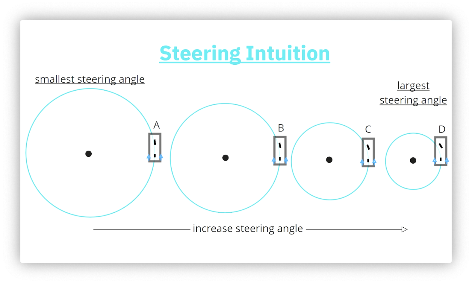
Circle Center Examples
The following diagram illustrates the relationship between the magnitude of the steering angle and the radius of the circle drawn by the rear axle of the robot. The smallest steering angle produces the largest circle, while the largest steering angle produces the smallest circle. As the radius of the circle decreases, its center moves closer to the robot.
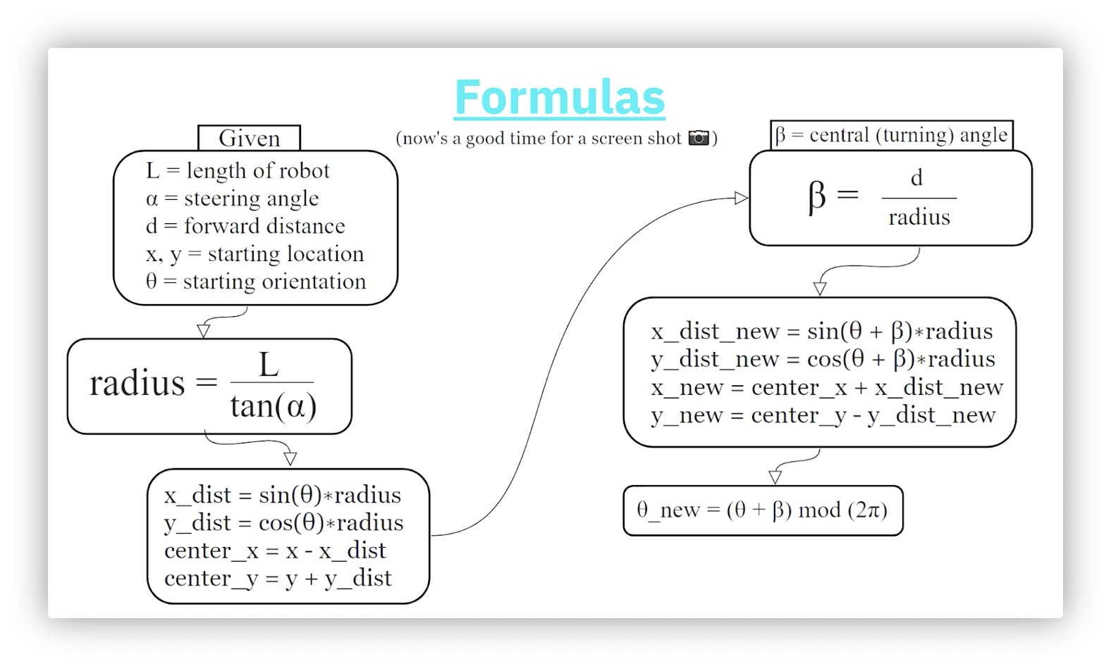
Step 1: Radius
To calculate the final pose after the compound movement, we must first determine the radius of the circle drawn by the rear axle. Consider the following figure.
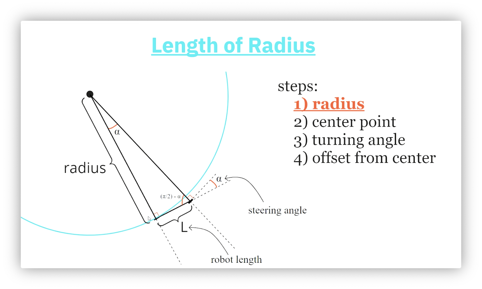
We construct a triangle by drawing lines from each axle - perpendicular to each axle - that intersect at the center of the circle. The length of the shortest side of this triangle is the length, , of the robot, and the length of the line from the rear axle to the center of the circle is the radius, .
We know that the lines connecting the axles to the center of the circle form right angles with the axles they intersect. Additionally, we label the steering angle, , as the angle the front axle makes with the robot's orientation. Because the sum of angles on a straight line must equal radians, the interior angle of our triangle must equal radians. The sum of the angles in a triangle must also equal radians, so the third angle in our triangle must equal radians.
We now use trigonometry to calculate the radius of the circle. Since , then .
Step 2: Center Point Location
Next, we need to determine the coordinates, , of the center of the circle whose radius we just computed. Consider the following diagram.
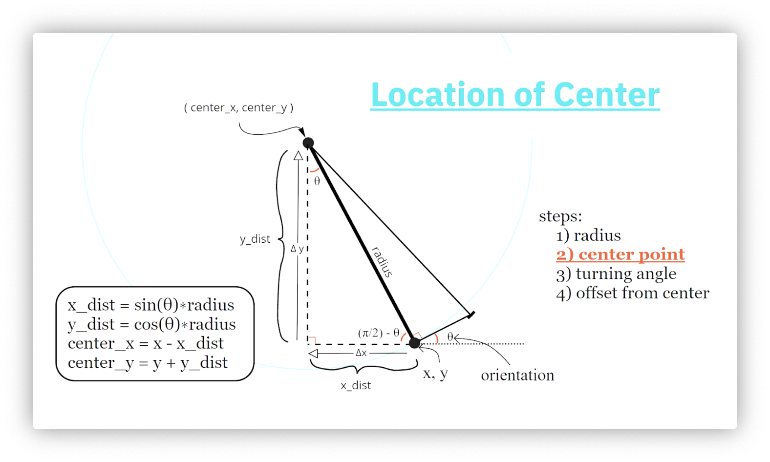
We start by constructing a new right triangle with the circle's radius, , as its hypotenuse. The length of the triangle's horizontal side, , is the difference between the x-coordinates of the robot and the circle's center. Similarly, the length of the triangle's vertical side, , is the difference between the y-coordinates of the circle's center and the robot.
How do we calculate the interior angles of the triangle? We know that the robot's angle with the horizontal is the orientation, . Because the sum of angles on a straight line must equal radians, the interior angle of our triangle must equal radians. The sum of the angles in a triangle must also equal radians, so the third angle in our triangle must equal radians.
We now use trigonometry to compute the length of the triangle's sides: since , and , then and . Finally, we calculate and . Note that we must travel a negative horizontal distance and a positive verticle distance from the robot to reach the circle's center.
Quiz: Return to Same Point
Given what we know so far, what distance must the robot travel to return to its current position? Assume a fixed steering angle.
Quiz Solution: Return to Same Point
The robot must traverse the circumference of the circle, , to return to its original position. Here, is the radius we found by dividing the robot's length by the tangent of its steering angle.
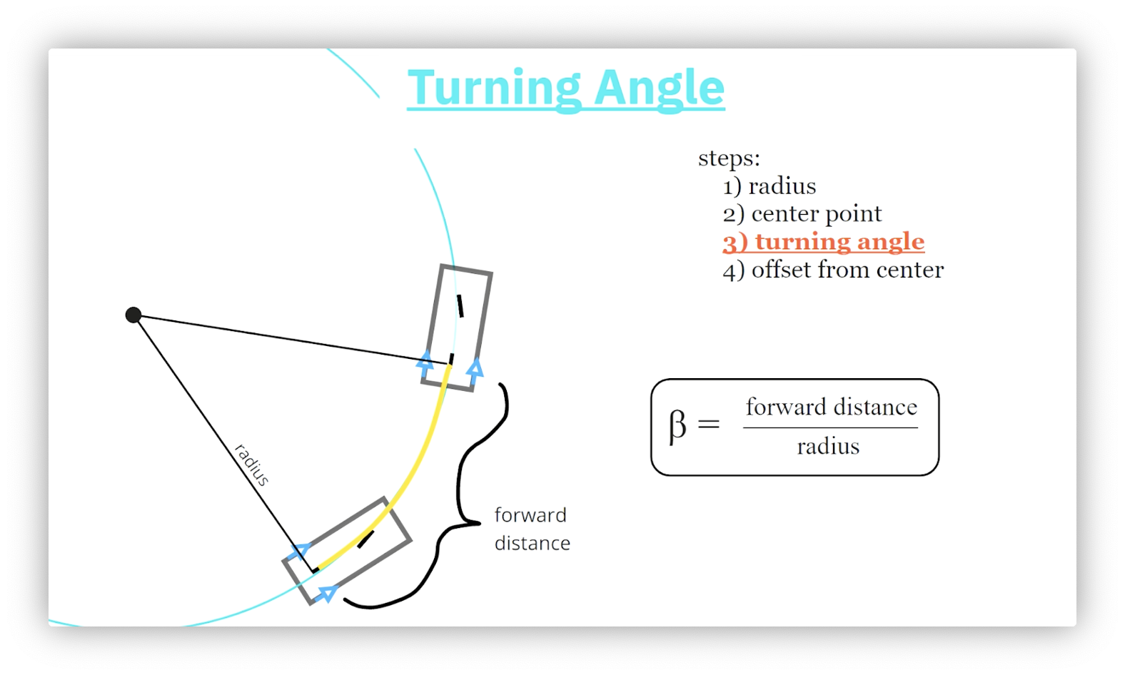
Step 3: Arc Length
An arc length, , is the distance between two points on the circumference of a circle. Given a central angle, , and a radius, , . In our case, we know and , so .
How do we know ? Remember the forward distance, ? When we issue a forward motion, that motion takes place along the circle's circumference. In other words, .
Step 4: Offset from Center
We determine the robot's final location by calculating the robot's x- and y-offset from the center of the circle using the central angle we just computed. Consider the following diagram.
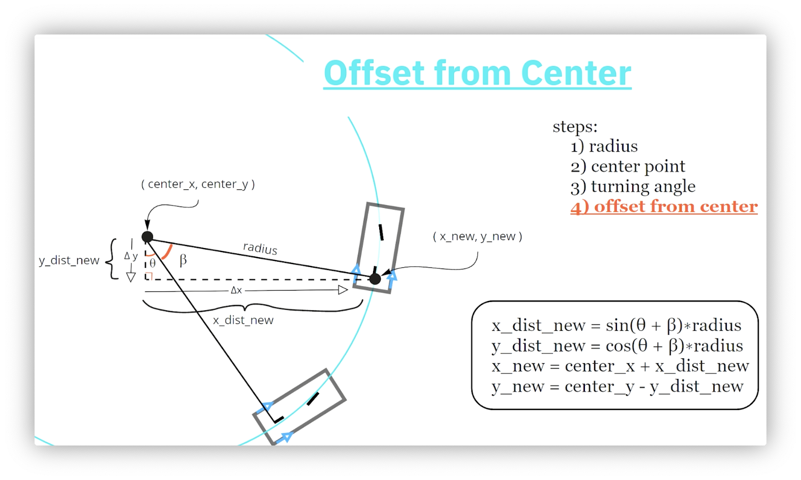
First, we draw a right triangle with one vertex at the circle's center and another at the robot's rear axle. This triangle's hypotenuse is . The angle associated with the vertex at the circle's center is .
Confused why appears here? Revisit the circle center calculation step and compare that right triangle to the one involving in this step.
We first calculate the length of the horizontal and vertical sides of the triangle using trigonometry. Next, we travel those distances from the circle's center to arrive at the robot. Using the diagram above, we must travel in the negative y-direction and positive x-direction. Our final set of equations is:
New Orientation
Calculating the robot's new orientation is the last step in computing the robot's final pose. Consider the following diagram.
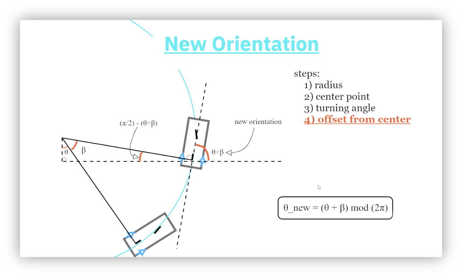
Let's start with the triangle we just drew. What is the value of its third interior angle? The sum of the angles in a triangle must equal radians, so the missing angle must equal radians.
Recall that the robot's orientation is its angle with the positive x-axis. Because the sum of the angles on a straight line must equal radians, the interior angle of our triangle must equal radians.
Confused about how we got the second right angle? The rear axle forms a tangent line to the circle, which we know must be perpendicular to its radius.
Our final equation is:
Formulas
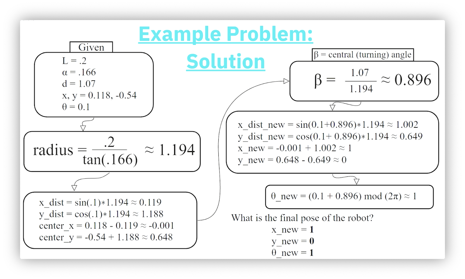
Quiz: Example Problem
Consider a robot of length with starting pose . After applying a steering angle of and a forward motion of , what is the final pose of the robot?
Quiz Solution: Example Problem
OMSCS Notes is made with in NYC by Matt Schlenker.
Copyright © 2019-2023. All rights reserved.
privacy policy