Computer Networks Old
Router Design Basics
6 minute read
Notice a tyop typo? Please submit an issue or open a PR.
Router Design Basics
Router Design
Here are two modern router chassis.
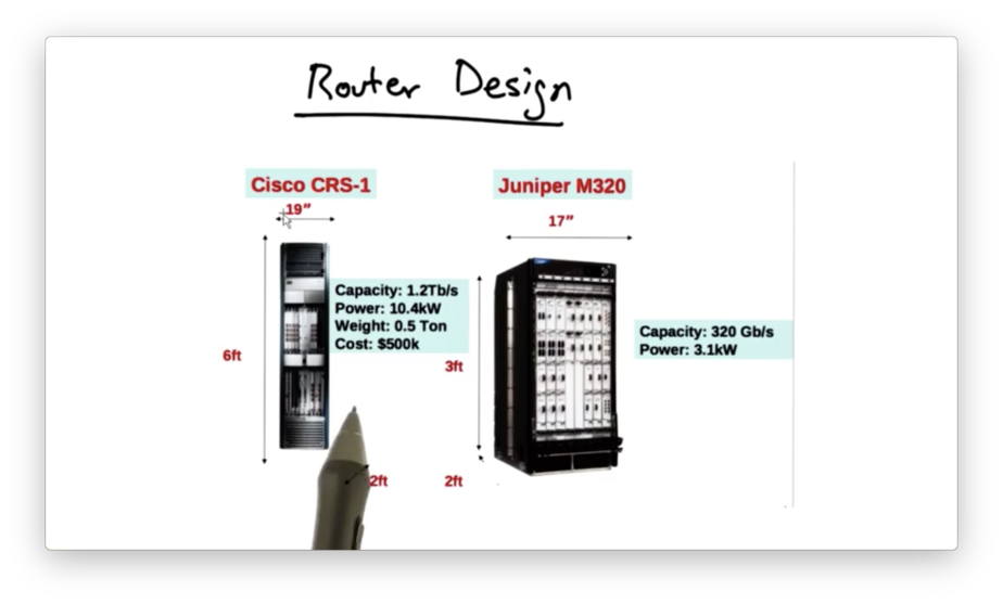
A chassis houses line cards, which actually perform the routing.
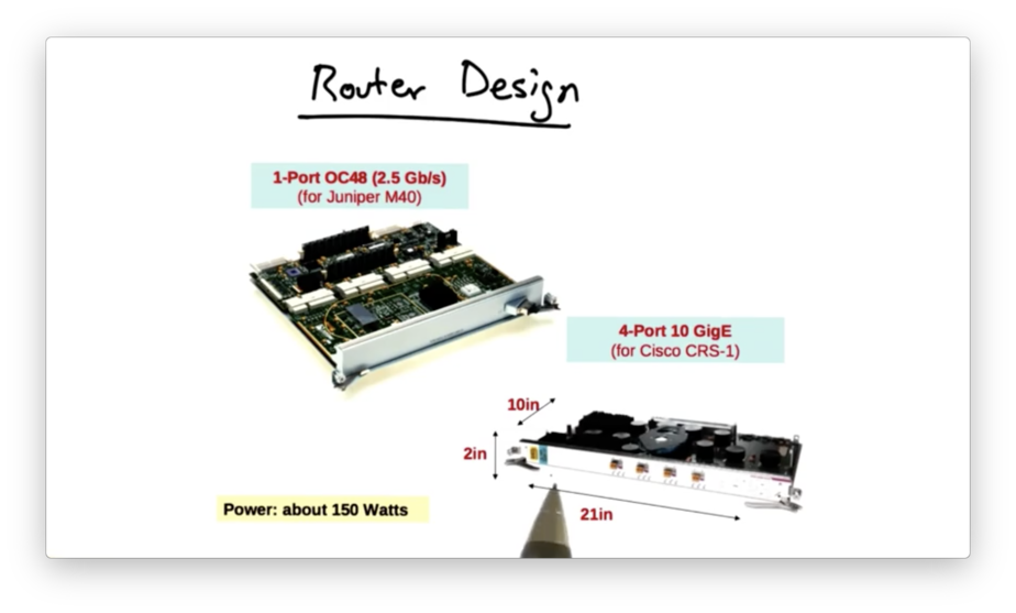
While these cards look like standard network interface cards, they are much larger and terminate with high capacity fiber instead of Ethernet.
There is a significant need for big, fast routers:
- Links are getting faster
- Traffic demands are increasing - particularly with the rise of streaming video applications
- Networks are getting larger, in terms of hosts, routers and users
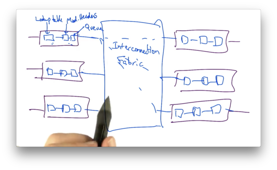
Basic Router Architecture
The basic I/O component of a router architecture is a line card, which is the interface by which the router sends and receives data.
When a packet arrives, the line card looks at the header to determine the destination, and then looks in the forwarding table to determine the output interface. It then updates the packet header - decrementing the packet's TTL, for example - and sends the packet to the appropriate output interface.
When a packet is sent to the output interface, it must traverse the router's interconnection fabric to be sent to the appropriate output port.
Each Line Card Has Its Own Forward Table Copy
One important decision in the design of modern routers was to place a copy of the forwarding table on each line card in the router.
While this introduces some complications in making copies of the forwarding table, doing so prevents a central table from becoming a bottleneck at high speeds.
Early router architectures did not place a copy of the lookup table on each line card. As a result, when packets arrived at an individual line card, it would induce a lookup in a shared buffer memory which could be accessed over a shared bus.
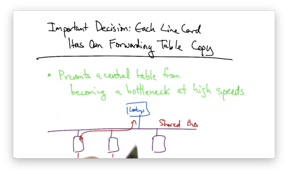
The shared bus introduces contention amongst all of the line cards that may be attempting to perform lookups at the same time to the same shared memory.
The solution was to remove the shared bus and instead place forwarding tables on each line card.
Decision: Crossbar Switching
A second important decision was the design of the interconnect; that is, how the line cards should be connected to one another.
One possibility is to use a shared bus. However, the disadvantage of a bus is that it can only be used by one input/output combination in any single time slot.
We would like to enable non-competing input/output pairs to send traffic from input to output during the same time slot.
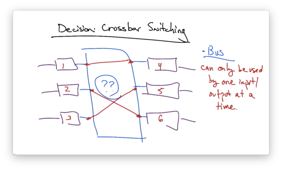
This solution is called crossbar switching.
Crossbar Switching
In crossbar switching, every input port has a connection to every output port. During each time slot, each input is connected to zero or one outputs.
The advantage of this design is that it exploits parallelism: it allows multiple packets to be forwarded across the interconnect in the same time slot.
For this solution to work, though, we need proper scheduling algorithms to ensure fair use of the crossbar switch.
Switching Algorithm: Maximal Matching
In a particular time slot, we may have a certain set of traffic demands; that is, we have traffic at certain input ports destined for certain output ports.
Given these demands, our goal is to produce a mapping that is maximal and fair. By maximal, we mean that the largest number of inputs are connected to the largest number of outputs.
Even with this goal, not all demands may be satisfied. Packets that arrived at inputs not currently connected to outputs must wait until the next time slot to be forwarded to the appropriate output port.
More router crossbars have a notion of speedup whereby multiple matchings can be performed in the same time slot.
If the line cards are running at 10Gbps, for example, running the interconnect twice as fast would allow matchings to occur twice as fast as packets would arrive on the inputs or be forwarded from the outputs.
It is common practice to run the interconnect at higher speeds than the input/output ports.
Head of Line Blocking
Just speeding up the interconnect does not solve all problems.
For example, if our input port is currently matched to output port A, and the head of the queue contains a packet destined for output port B, the entire queue will not be able to move until the packet for B is cleared.
This is referred to as head of line blocking.
A solution is to create virtual output queues. Instead of creating one queue at the input, we maintain one queue per output port. This prevents packets at the front of the queue, destined for one output port, from blocking packets that could otherwise be matched to other output queues in earlier time slots.
Scheduling and Fairness
The decision about which ports should be matched in any particular time slot is called scheduling.
One goal of scheduling is efficiency. If there is traffic at input ports destined for output ports, the crossbar switch should schedule inputs and outputs so traffic isn't sitting idly at the input ports if some traffic could be sent to the available output ports.
Another scheduling consideration is fairness. Given demands at the inputs, each queue at the input should be scheduled fairly, for some definition of fairness.
Defining fairness is tricky, and there are multiple possible definitions of fairness.
Max-Min Fairness
One type of fairness is max-min fairness.
To define max-min fairness, let's first assume that we have some allocation of rates {x1, x2 … xn } across flows. We say that this allocation is "max-min fair" if increasing any rate xi implies that some other rate xj, where xj < xi, must be decreased to accommodate for the increase in xi.
Put another way, the allocation is max-min fair if we can't make any rate better off without making an already worse off rate even worse.
The benefit of max-min fairness is that small demands being met in full, while large demands split the remaining capacity amongst themselves equally.
Example
Let's consider the following example.
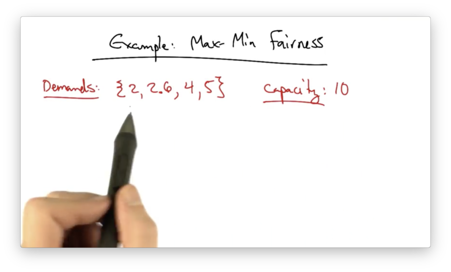
Obviously, the demands exceed the capacity, so we need to figure a way of allocating rates to each of these demands that is max-min fair.
To start, let's divide the capacity by the number of demands to achieve a completely fair allocation of rates.
Our initial distribution is {2.5, 2.5, 2.5, 2.5}.
This is not a good solution: the first flow will have an excess of 0.5.
What we can do is take this excess of 0.5, and divide it among the remaining three flows, whose demands (all greater than 2.5) have not yet been met.
Since 0.5 / 3 is 0.167, our new distribution will be {2, 2.67, 2.67, 2.67}.
Now our second flow has an excess of 0.07. We can redistribute this excess across the remaining two flows, at 0.035 / flow.
Our final distribution will be {2, 2.6, 2.7, 2.7}.
How to Achieve Max-Min Fairness
One approach to achieve max-min fairness is via round robin scheduling where, given a set of queues, the router simply services them in order.
The problem with round robin scheduling is that packets may have different sizes.
If the first queue has a large packet and the second queue has a small packet, the first queue will essentially get more of its fair share just because its packet happened to be bigger.
Alternatively, we can use bit-by-bit scheduling where, during each time slot, each queue only has one bit serviced.
While this is perfectly fair, this is difficult from a feasibility standpoint. How do we service one bit from a queue?
A third alternative is called fair queueing which achieves max-min fairness by servicing packets according to the "soonest finishing time".
A fair queueing algorithm computes the virtual finishing time of all candidate packets, which are the packets at the head of all non-empty flow queues. The scheduler then services the queue with the minimum finishing time.
OMSCS Notes is made with in NYC by Matt Schlenker.
Copyright © 2019-2023. All rights reserved.
privacy policy